> Potentiometer Joystick, Hall Effect Joystick, Inductive Joystick & Optical Joystick from CTI Electronics
CTI Electronics Corporation Logo

www.betatronix.com


CTI Electronics Telephone Number: +1 203-386-9779

CTI Electronics ISO 9001:2015 Certificate No. 743003983

CTI Electronics Product Brochure
CTI Google+ Link CTI Facebook CTI Linkedin CTI Twitter CTI Youtube Videos CTI News Articles

Potentiometer, Hall Effect, Inductive, Optical Joystick

Understanding the Progression of Joystick Technologies


Let us tell you a story of the “joystick”.  Prior to being called a joystick it was known as a “control lever”, “handle” or just a “stick".  It involved mechanical linkages between a person and a physical device (apparatus) that needed to move in one direction or the other.  The problem soon became apparent that a person could only control that apparatus based upon their own physical limit of the amount of force that could be applied to the mechanical control lever.  It wasn’t until the knowledge of adapting electrical circuitry (specifically the changes in voltages or current levels) that the idea of controlling physical devices (mechanical components) that required much more force than a person could possibly exert upon the handle or lever that the invention of the “joystick” became a reality.  The person who needed to control a large or heavy object or even a very distant object could do so by applying a small amount of force to a “stick” and accomplish tasks with relative ease or “joy”, in doing so the term “joystick” was coined.  It became so widespread, so quickly, that today it is known around the globe only as a “joystick”, there is no direct translation of this word into any other language.


One of the first applications of the “joystick” was in the field of aerospace, where the control of the ailerons and elevators became a necessity.  This usage of electrical signals from the joystick to ultimately move a mechanical part of the plane in one direction or the other came to be known as “fly by wire”.  There are literally thousands of applications today that take advantage of electronic signaling joystick to control motion.
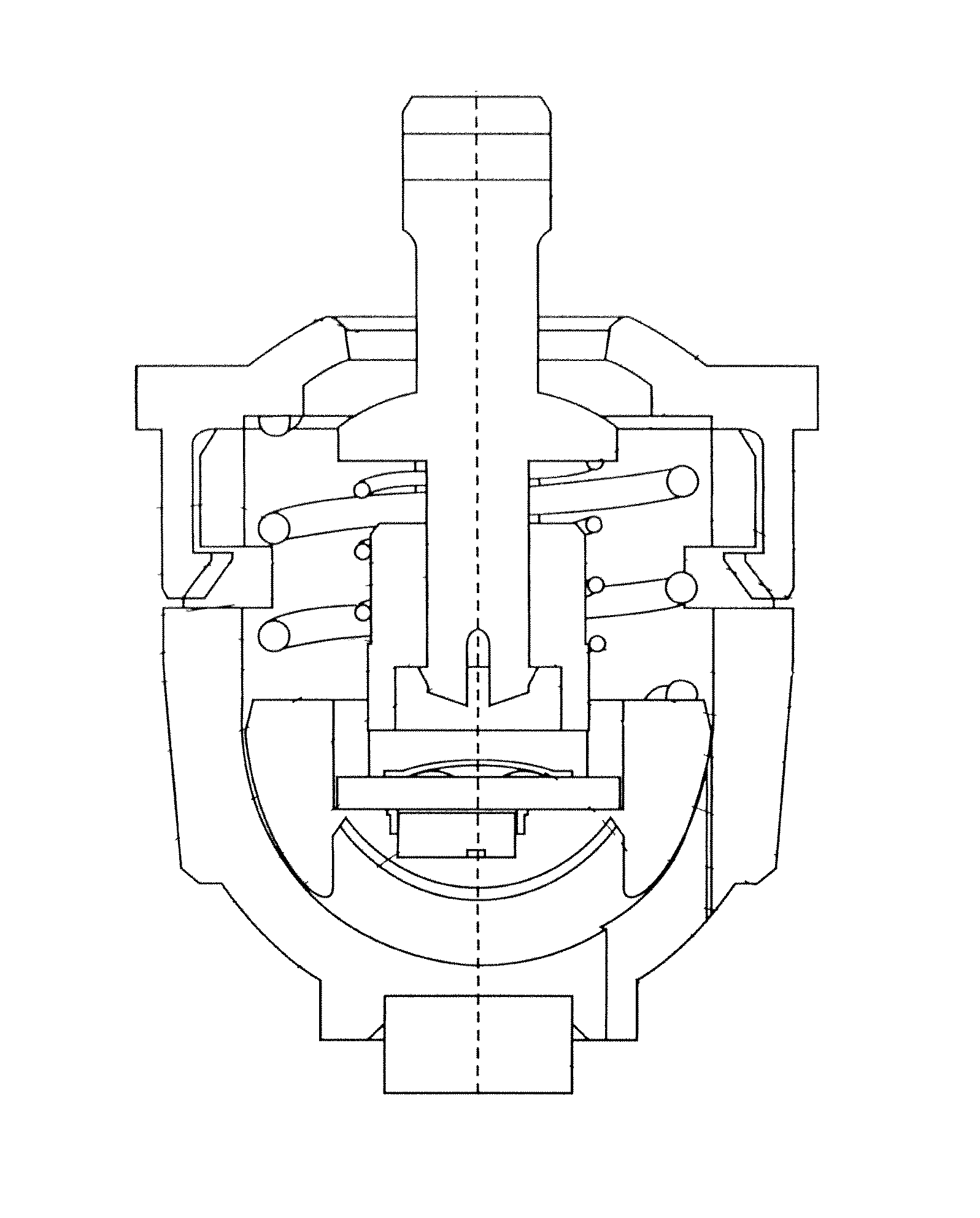

Potentiometer Joystick Example

Potentiometer Joystick

The first joystick took advantage of component of Ohm's Law which in the field of electricity known as resistance, most engineers refer to this type of joystick as a potentiometer joystick. The potentiometer joystick has physical components that when moved allow either the increase or decrease of voltage or current through the variance of resistance within the electronic circuit. This variance of voltage or current is easily accomplished by the operator of the potentiometer joystick with only a very small amount of force applied. The potentiometer joystick technology opened the doors for electronic circuit control but it has limitations in terms of long term durability and reliability due to the wearing of moving parts and minor susceptibility to electromagnetic interference or radio frequency interference.
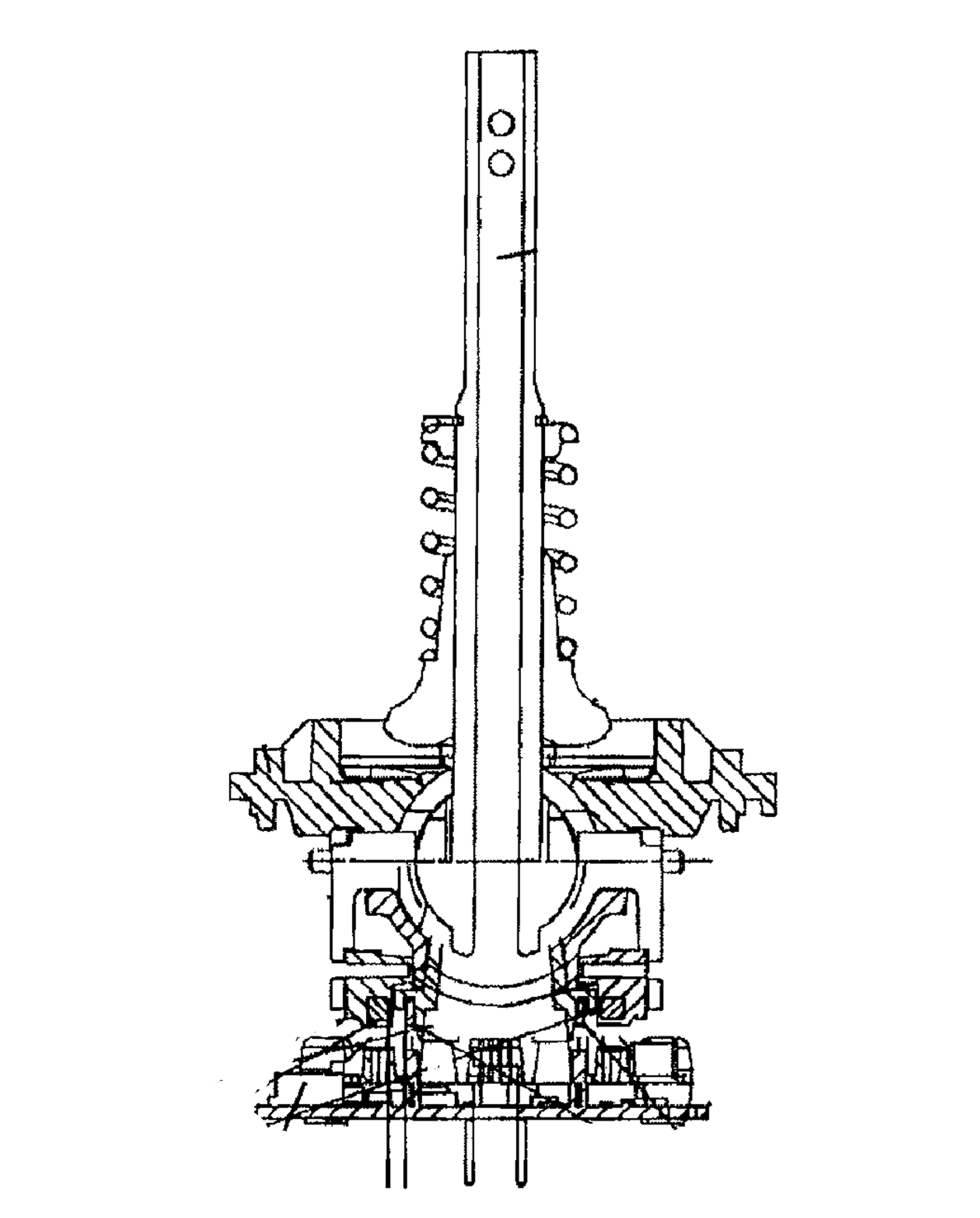

Hall Effect Joystick ExampleHall Effect Joystick

Another technology, discovered by Edwin Herbert Hall applies the properties of electromagnetism through the usage of ferromagnetic material, gave rise to the hall effect joystick. The hall effect joystick has an advantage over the potentiometer joystick in that there is no physical contacting wear issue with the sensor itself.  But the bails mechanism or gimbal mechanism for each magnet does move and will wear over time thus causing mechanical hysteresis. Also, the hall effect joystick does have a limitation in the very nature of the ferromagnetic material that is used, as it's magnetic field will change over time and is directly affected by temperatures (<0°C and >70°C). These variances in the magnetic field will cause the hall effect joystick to "drift". That is, the output voltage of the hall effect joystick will unwantedly vary and cause undesired effects. So the long term reliability of the hall effect joystick is limited.
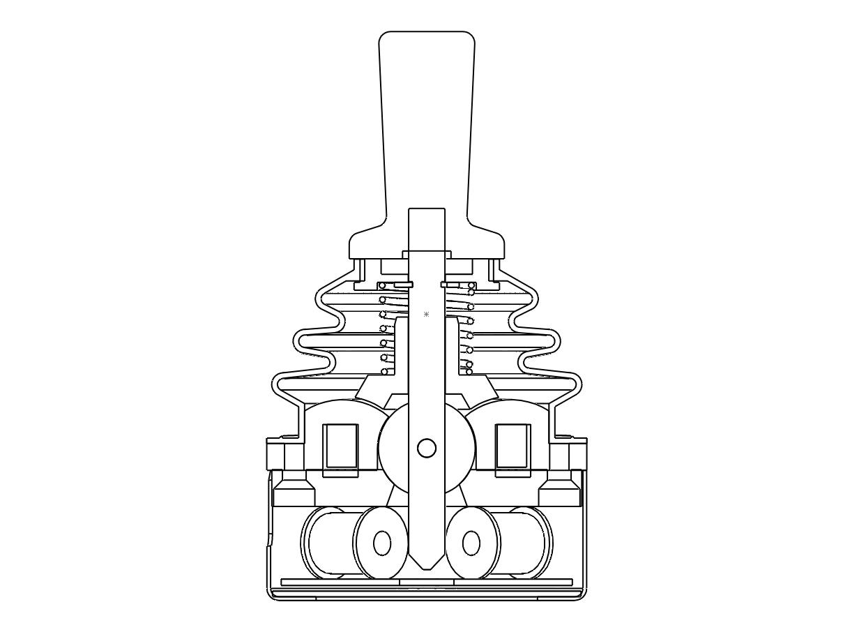

Inductive Joystick Example

Inductive Joystick

With the limitations of reliability and durability that the potentiometer joystick and hall effect joystick offered a third technology using Faraday's Law of Induction gave rise to the invention of the inductive joystick. This technology uses a toroidal coil (a set or sets of coiled copper wires laid out in a circular format) to which a current is applied inducing a magnet field. A metal shaft is then placed within the toroidal coil, when moved within this magnet field it cuts through or interferes with the magnetic lines of force thus inducing a change in the flow of current in the coil(s). The change in current flow is correlated to a change in the proportional voltage output provided by the inductive joystick. This technology increases the reliability and durability of the inductive joystick in that the number of moving parts is limited to the shaft, spring, and boot. It eliminates the problem of "drifting" found in the potentiometer joysticks and hall effect joysticks since there is no electronic component that degrades over time. There is one issue that does need to be addressed with the inductive joystick is that of susceptibility to interference by extraneous electromagnetic of radio frequency signals. With proper shielding of the toroidal coil and cable wiring outside EMI/RFI can be mitigated.

Optical Joystick

There is a "newer" technology that CTI Electronics is now making available through optical position sensing of the joystick shaft using wavelengths of light, this patented optical joystick is known as CTI's Ligthstick®. The optical joystick has only advantages over the inductive joystick, hall effect joystick, and potentiometer joystick. The design is such that any degradation to the LED light sources by time or temperature are compensated by a patented redundant differential light sensor design within the optical joystick, thus having zero effect on its reliability or durability. Problems associated with drifting, recalibrating, worn physical components, susceptibility to electromagnetism, radio frequency interference, high vibration and shock have been mitigated with the introduction of the optical joystick. Compromise on one area of reliability vs. another or the long term durability of the joystick in harsh environments is eliminated with the application of CTI's optical joystick, Lightstick®.

CTI Electronics LightStick®

CTI's optical joystick is first being offered in the L-1000 Series which will look similar to the F-1000 Series but has its unique advantages such as a completely encapsulated analog printed circuit board. This is a simple one step installation process with the added advantage of a below depth panel requirement of ¾ (1.9cm) of an inch. The L-1000 Series optical joystick line is perfect for modern solid state circuitry design having low powered +5vdc or +3.3vdc usage. In the product planning stages are the L-2000 Series which will use the optical joystick technology with a larger form factor (handle), typically needed in outdoor environments and off road applications. Also planned, is the L-4000 optical joysticks having a "grip style" format with optional switches and buttons typically found in heavy equipment such as farming, construction, or aviation. We hope this background of the progression of joystick technology was informative and we welcome your feedback. The application of the optical joystick is the superior design solution surpassing all other joystick technologies in terms of reliability and durability. We invite OEM's and Systems Integrators to take advantage of the optical joystick technology.


Manufactured in U.S.A. Manufactured in U.S.A. Copyright © 2001-2013 | CTI Electronics Corporation | Tel: (203) 386-9779 | All Rights Reserved - sitemap | Sales | Tech